Product Description
1. Introduction of SNCR process
SNCR is a method for reducing NOx in the range of 850-1100 ℃ without using a catalyst. SNCR technology is to spray a reducing agent such as ammonia and urea into the furnace temperature range of 850-1100 ℃, the reducing agent is quickly thermally decomposed into NH3 and SNCR reaction with NOx in flue gas to generate N2 and H2O. In this method, the furnace is a reactor, which can be realized by transforming the boiler. SNCR reactant storage and operating system is similar to SCR system, but it requires higher amounts of ammonia and urea than SCR process.
In the narrow temperature range of 850-1100 ° C in the furnace, without catalyst, amino reducing agents such as ammonia or urea can selectively reduce NOx in the flue gas, and basically do not react with O2 in the flue gas, mainly The reaction is:
Ammonia is the reducing agent:
NH3 + NOx → N2 + H20
Urea is a reducing agent:
CO (NH2) 2 → 2NH2 + CO
NH2 + NOx → N2 + H20
CO + NOx → N2 + CO2
When the temperature is too high and the reaction temperature window is exceeded, ammonia will be oxidized to NOx:
NH3 + O2 → NOx + H20
The NOx removal efficiency of the SNCR process mainly depends on the reaction temperature, the stoichiometric ratio of NH3 and NOx, the degree of mixing, the reaction time, etc. The temperature control of the SNCR process is very important. The optimal reaction temperature is 950 ℃. If the temperature is too low, the NH3 reaction is incomplete, which easily causes NH3 leakage; while the temperature is too high, NH3 is easily oxidized to NOx, which offsets the Removal efficiency. If the temperature is too high or too low, the loss of reducing agent and the NOx removal rate will decrease.
2. Schematic diagram of SNCR ammonia and urea
3. Basic layout of SNCR ammonia and urea
1.1 Ammonia water reducing agent
1.2 Urea reducing agent
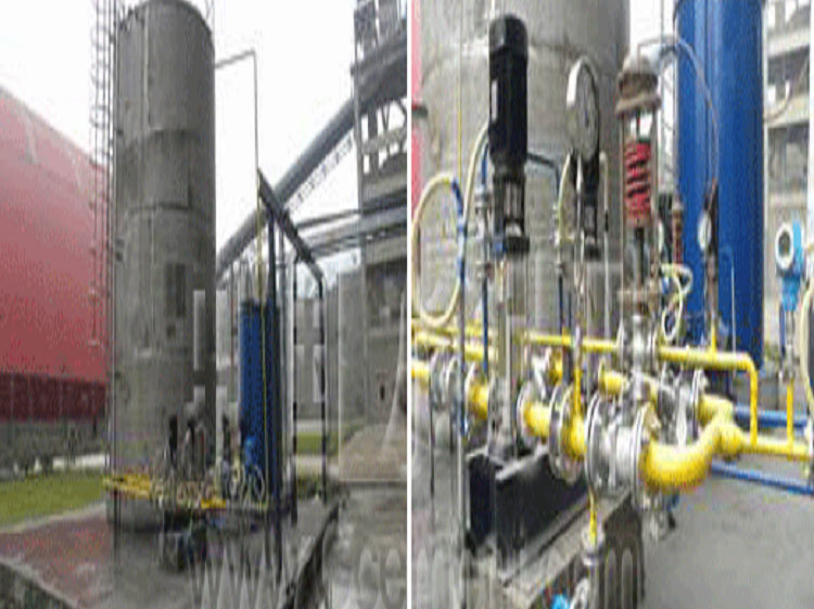
4. Case
Gun installation
Metering module picture
Ammonia installation
SNCR Denitration System Operation Rules
1 Overview
Nitrogen oxides (NOx) are one of the main sources of air pollution. China's environmental protection policy requires that cement plants manufacturing cement clinker should strictly control large amounts of NOx emissions. The technical indicators for controlling NOx emissions can be divided into two categories: primary measures and secondary measures. The primary measures are to reduce the amount of NOx produced in the combustion process through various technical means; Removed.
The denitration project of Tongchuan Shengwei Building Materials Co., Ltd. uses the SNCR selective non-catalytic reduction method of flue gas automatic denitration system. The reducing agent (ammonia water) is injected into the decomposition furnace with normal combustion conditions to burn the furnace to generate flue gas. NOx is reduced to N2 and H2O, which reduces NOx emissions and creates a reduction zone to reduce the amount of NOx generated during combustion.
2 Process description
2.1 Ammonia liquid storage tank and filling system, the system is equipped with two 80m³ bedroom type ammonia liquid storage tanks, the top is equipped with overflow protection switch and breathing valve, and the top is provided with a liquid level meter and ammonia water direct discharge door.
The ammonia liquid is sent by a special tank truck, and the vehicle's own hose is used to connect the inlet pipe and circulation pipe of the filling pump through the quick interface. The ammonia liquid is generally 20% -25% ammonia water. The ammonia filling pumps are two centrifugal pumps, with switches on the outlet valve and circulation valve handles. When the power of the filling pump is sent, the outlet valve and the circulation valve are opened, and when the ammonia tank is not full, the filling pump can be started to fill the ammonia tank.
For safety, there is an emergency tap device for running water next to the ammonia storage tank, which is used to flush eyes and skin in case of emergency for protective pretreatment.
The SNCR ammonia water supply pump system is equipped with a set of ammonia water pressurization pump group next to the ammonia tank. The ammonia liquid is drawn from the bottom of the ammonia water storage tank. Processing unit. There are 2 stainless steel multistage centrifugal pumps in each group of jet pressure pumps, one for each use. In addition to the manual isolation valve at the inlet of each pump set, there is also an electrically controlled pneumatic isolation valve to realize the remote control switch. The compressed air source is taken from the factory's compressed air station; the outlet is equipped with a remote pressure gauge. Each booster pump is equipped with manual inlet and outlet isolation valves and outlet check valves.
There is also an ammonia leak detector at the site to prevent the ammonia water from leaking too much, and spray to reduce the concentration. The ammonia storage tank is equipped with a liquid level gauge, and the ammonia booster pump is stopped when the liquid level is low.
The ammonia water from the SNCR system injection pressurization pump is sent into the injection ring pipe through their respective electrically controlled pneumatic valves, filters, flow meters and regulating valves to meet the control requirements of the cement line NOx. Each pipeline is equipped with a check valve to prevent the backflow of ammonia water and tap water, especially to prevent the leakage of ammonia water. There is also a tap water flushing ammonia water pipeline. The SNCR system can flush the ammonia water pipeline during shutdown and maintenance to ensure that no ammonia water remains in the pipeline.
2.2 SNCR injector
The SNCR injector is made of stainless steel, double-layer casing, ammonia water goes in the middle, the factory compressed air is regulated by the pressure regulating valve to 0.35-0.45MPa, then go to the outer layer, cool the spray gun and spray head, and pass the spray nozzle mist Ammonia water is sprayed into the furnace.
The ejector is connected with ammonia water and compressed air hose with a hose. It is installed on the protective sleeve of the hole in the front wall of the calciner with a quick plug connector with a spring lock. It is arranged in a single layer and a total of 6 spray guns, including automatic access Control device.
2.3 Other
The control and regulation module is equipped with intelligent PLC Siemens S7-300, distributed I / O, bus communication. Fully automatic control, management, coordination and monitoring of all process functions. It communicates with its own DCS and accepts relevant operating parameters and control signals. The field control cabinet is equipped with an industrial computer with a touch screen as a man-machine interface to realize the operation and monitoring of SNCR.
3 Operation control
3.1 Ammonia filling
3.1.1 Ammonia water storage tanks can only be filled with ammonia water on the on-site operation panel of the control box;
3.1.2 Except for professional operators, other personnel shall not be close to the filling site;
3.1.3 The operator must use personal safety equipment as required, and take good safety measures;
3.1.4 Check and select a filling pump as the working pump, select "AUTO" as the control, send the power to the equipment, and the power indicator of the control box lights up;
3.1.5 Connect the inlet hose of the ammonia tank truck to the inlet of the receiving pump;
3.1.6 Open the tank truck drain valve;
3.1.7 Open the ammonia water filling valve; check the status of the status indicator light of the on-site control box;
3.1.8 Press the start button on the control box interface to start the filling pump;
3.1.9 Filling is completed, first empty the hose, then press the stop button to stop the pump, and immediately close the ammonia filling valve;
3.1.10 Install the quick plug on the pipeline immediately after removing the hose.
3.2 Commissioning of SNCR
3.2.1 Preparation before starting the SNCR ammonia booster pump system
3.2.1.1 There is no abnormality in the ammonia leak detection in the inspection area, and the level of the ammonia water tank is normal;
3.2.1.2 Select a booster pump as the working pump, close the pump safety switch, reset the emergency stop button, and send the device power;
3.2.1.3 Check to open the inlet and outlet isolation door of the pressure pump and close the inlet drain door;
3.2.3 Preparations before starting the SNCR processing unit
3.2.3.1 Check that there is no abnormality in ammonia gas leak detection;
3.2.3.2 Open the instrument-controlled compressed air isolation door and check that the instrument-controlled compressed air pressure is normal;
3.2.3.3 Open each manual isolation door of ammonia liquid pipeline;
3.2.3.4 Open each manual isolation door of the tap water pipeline;
3.2.3.5 Open the isolation doors of the injector and fully open the ball valves;
3.2.3.6 Check that all flowmeters and pressure sensors in the power supply are normal and show no abnormality;
3.2.3.7 Check that the status of each pneumatic valve is correct.
3.2.4 Preparation before starting the injector
3.2.4.1 Check that the injectors are installed and in place, and the quick-plug inlet connection is normal;
3.2.4.2 Check that the ammonia hose and atomizing air hose of each injector are properly connected;
3.2.4.3 Check that the pressure of the atomizing air reducing valve of each injector is normal, about 4 bar.
3.2.5 Putting into operation of SNCR automatic denitration system
3.2.5.1 Check that there is no alarm that affects the startup of the computer interface on site;
3.2.5.3 Check the SNCR ammonia liquid supply pump shows that the working pump is consistent with the scene; check that the pneumatic valve has been selected in "working state", the pressure and liquid level display are normal, and there is no abnormal alarm;
3.2.5.4 Enter the "working state", check that the electronically controlled pneumatic valves have been selected in the "working state", the regulating valve is also selected to be automatic, the parameters have been set normally, and the NOx control LOOP has been assigned as required
3.2.5.5 Click "Run" to check that the SNCR system is automatically put into operation;
3.2.5.6 Check the flow of ammonia water in the cabinet of the SNCR processing unit. The flow and pressure of the ejector loops of each layer are uniform. If necessary, close the needle valve of the pipeline with a small flow and a large flow to adjust the flow of each ejector; ;
3.2.5.8 Check that the SNCR ammonia booster pump system is working properly and the outlet pressure is normal.
3.2.5.9 Check whether the NOx index of the flue gas analysis meets the requirements, otherwise you can log in and enter the input screen to set the parameters, including the total ammonia flow rate, the ammonia flow rate of each layer of injectors, and the number of injectors that can be used.
3.2.6 Outage of SNCR automatic denitration system
3.2.6.2 Select "Stop" on the central control operation interface, the system will automatically stop operation after executing the flushing procedure;
3.2.6.3 SNCR can also be stopped on the SNCR screen in the control room.
4. Equipment maintenance
4.1 Maintenance of ammonia tank
4.1.1 The ammonia tank needs to be checked for leakage once a year;
4.1.2 The filling port at the top needs to be inspected once a year;
4.1.3 The breathing port on the top should be checked once a year;
4.1.4 If the ammonia tank needs to be emptied for any reason, first turn off the valve in front of the level gauge, remove the transmitter, close the inlet valve of the ammonia water pressure line, carefully open the manhole door, clean, and ventilate To enter the ammonia tank.
4.2 Maintenance of SNCR ammonia pump supply system
4.2.1 Check whether there is leakage in the pipeline during operation and whether the pump works normally;
4.2.2 Check whether the pump outlet pressure is normal, and adjust and protect the safety of the equipment if necessary;
4.2.3 Check the ammonia leak detector at least twice a year;
4.2.4 Periodic switching and testing system according to the equipment, switching working and standby pumps every month.
4.4 Maintenance of SNCR processing unit
4.4.1 Check that there is no leakage of ammonia and tap water pipelines, and there is no abnormality in the ammonia leak detection of control cabinets;
4.4.2 Check that the pressure of the SNCR processing unit instrument-controlled compressed air is normal;
4.4.3 Ammonia water line filter and tap water line filter should be cleaned regularly twice a year. If it is suspected to be blocked during operation, if the opening of the regulating valve is not fully open, the filter screen should be cleaned;
4.4.4 Check that the flow and pressure of each injector of the injector module are normal and the flow and pressure are balanced. If the flow deviation is large, the needle valve of the injector line with a large adjustment flow can be closed to increase the flow of other pipelines accordingly;
4.4.5 Before disassembling the pipeline, flush the pipeline and take safety measures.
4.4.6 Check the ammonia leak detector twice a year.
4.4 Maintenance of SNCR injector
4.4.1 Check that the atomizing compressed air pressure regulating valve of each injector works normally, and the pressure is 3.3-4.5 bar;
4.4.2 Check the injector at least once a month;
4.4.3 If the flow rate of an injector is still low after the needle valve of the middle injector module is adjusted, the nozzle of the injector may be blocked, and the spray gun should be taken out to check and clean the nozzle;
4.4.4 Before removing the ejector, flush the pipeline gun, stop the ejector, close the gas and water isolation door, and stop the SNCR system if necessary;
4.4.5 If necessary, use a weak acid such as citric acid to clean the slurry on the atomizing nozzle, or remove the outer protective tube and clean the atomizing nozzle with thin metal wire or compressed air. When the slurry is serious, the entire spray gun can be removed and washed with hydrochloric acid.